


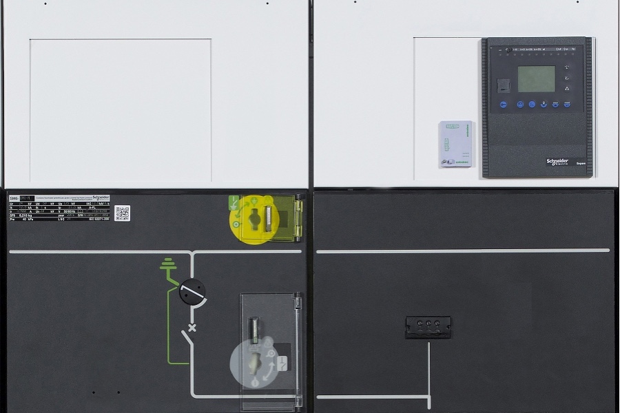
In medium voltage (MV) power systems—typically operating between 1 kV and 36 kV—switchgear controls, protects, and isolates electrical equipment. Because of the high energy involved, minor operational errors can cause equipment damage or personnel injury. Interlocking systems are a critical layer of protection that prevent unsafe operating sequences and ensure reliable operation.
Purpose of Interlocking Systems
Interlocks prevent unsafe or incorrect sequences by enforcing conditions before a device can operate. They stop operators from closing isolators onto live circuits, opening earthing switches under load, or closing breakers while the earthing switch is engaged. In short, interlocks are the mechanical and logical guardians of safe switching.
Types of Interlocks
Mechanical interlocks use physical linkages or key-transfer systems. A key must be released from the breaker compartment before it can be inserted into the isolator mechanism, guaranteeing a fixed order of operations. Mechanical systems are simple, reliable, and effective as a last line of defence.
Electrical interlocks use auxiliary contacts and control circuitry to inhibit operations unless predefined electrical conditions are met. They are essential for remote or motor-operated gear and integrate naturally with SCADA and PLC systems.
Logical or software interlocks are implemented in protection relays or IEDs. Programmable logic enforces complex conditions—such as synchronism checks, load-transfer rules, and coordination across multiple feeders—and is easily updated during system changes.
Typical Interlocking Sequences
A standard sequence for CB (circuit breaker), DS (disconnector/isolator), and ES (earthing switch) enforces that: the CB must be open before the DS can be operated; the ES can only close when the DS is open and voltage is absent; and the CB cannot close if the ES is engaged. These sequences prevent inadvertent energization and ensure personnel safety during maintenance.
Testing, Commissioning and Maintenance
Interlocks require verification at FAT and site commissioning. Tests should cover mechanical operation, auxiliary contact feedback, key-transfer integrity, and logic verification under simulated fault conditions. Periodic maintenance must inspect mechanical wear, contact reliability, and correct logic after firmware or control upgrades. Documentation of tests and tagout records is essential for compliance and auditability.
Human Factors and Procedures
Interlocks supplement but do not replace trained operators and clear procedures. Visible labelling, standardized operating instructions, and controlled access reduce human error and the temptation to bypass safeguards. Training programs should include hands-on practice and emergency recovery procedures. Where bypasses are necessary for testing, multi-person authorization and strict logging must be enforced.
Standards, Compliance and Best Practices
Design must adhere to applicable standards such as the IEC 62271 series and local safety regulations. Best practice combines layered protection: mechanical interlocks as fail-safe barriers, electrical interlocks for operational control, and logical interlocks for system coordination. Design for fail-safe behavior (safe state on loss of power), clear documentation, and controlled bypass processes are key.
Conclusion
Well-designed interlocking systems are indispensable in MV switchgear. When integrated with disciplined procedures, regular testing, and operator training, interlocks dramatically reduce the risk of switching errors, protect equipment, and increase system reliability. Balancing robust mechanical safety with intelligent control provides the safest, most resilient approach to medium voltage operations. For example, documented cases show interlocks and procedures combined reduce switching incidents significantly, and utilities should prioritize interlock audits during lifecycle reviews to capture latent risks before they cause outages and injuries.
Comments are closed