
SOLUTION 02 / 06
Transformers
UP TO 31.5 MVA · 36 kV
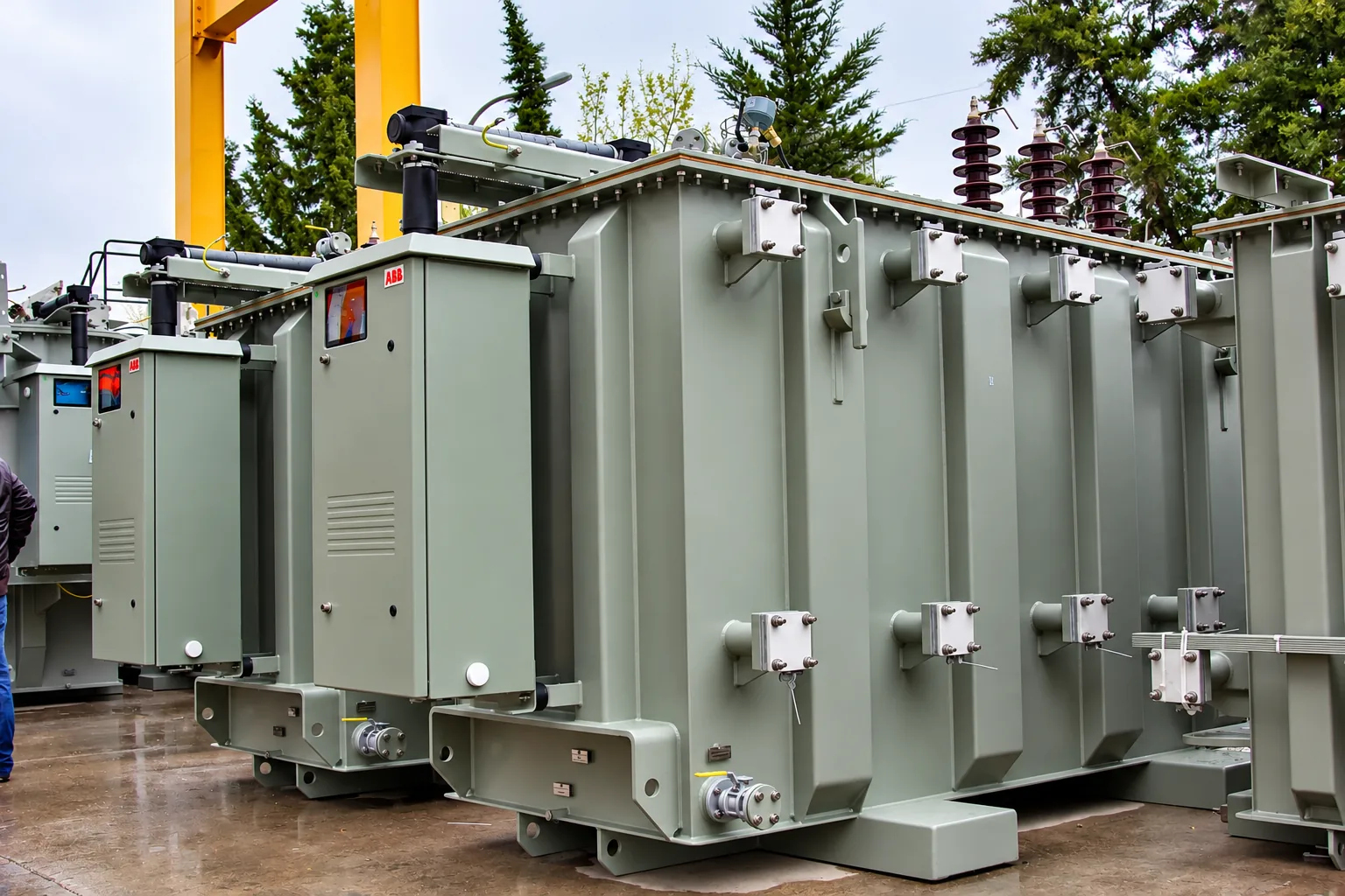
Oil-filled and cast-resin dry-type distribution and power transformers for utility, building, industrial and infrastructure projects.
Transformers are selected according to the required capacity, voltage ratio, cooling, installation conditions and project specification. We compare options from established international manufacturers and Türkiye’s electrical manufacturing capabilities, and keep the technical and commercial requirements connected through to integrated project supply.
EQUIPMENT SCOPE
Transformers we source
AdepaTrade sources oil-filled transformers up to 31.5 MVA (31,500 kVA), with voltage ratings up to 36 kV, according to project specifications and manufacturer capabilities. Ratings, options and accessories are confirmed for the specific unit; not every manufacturer offers every rating.
OIL-FILLED TRANSFORMERS
01
Oil-filled distribution and power transformers
Oil-immersed transformers for ground-mounted indoor or outdoor substations, compact / package substations and, at smaller ratings, pole-mounted overhead networks.
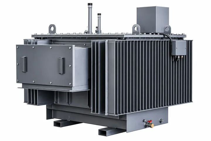
Configuration options
- Tank: Hermetically sealed or with conservator
- Cooling: ONAN; ONAF on specified designs
- Insulating liquid: Mineral oil or ester fluids
- Tapping: Off-circuit HV tappings; on-load tap changer where specified
- Protection and monitoring: Buchholz relay on conservator tanks, pressure relief valve, oil level and temperature indicators with contacts, or an integrated hermetic protection device
CAST-RESIN DRY-TYPE TRANSFORMERS
02
Cast-resin dry-type transformers
Transformers with resin-encapsulated windings and no insulating liquid, for indoor installations where the installation environment, fire performance and maintenance considerations influence selection.
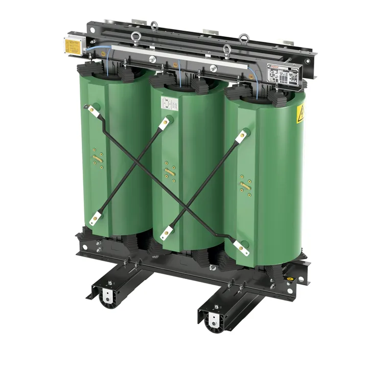
Configuration options
- Enclosure: Without enclosure (IP00) or in a ventilated enclosure, typically IP23 or IP31
- Cooling: AN; fans for a temporary increase in rating, or AF where specified
- Temperature monitoring: Pt100 or PTC sensors in the LV windings, with a temperature control unit
- Accessories: Surge arresters, anti-vibration pads and LV busbar-trunking interfaces
APPLICATIONS
Where these transformers are applied
These are general applications for distribution and power transformers.
Utility distribution networks
Secondary substations, ring networks and overhead lines, where network-operator requirements set ratings, losses and connection details.
Buildings and campuses
Commercial, institutional and residential developments, where indoor installation and fire performance often favour cast-resin units.
Industrial facilities
Plant substations supplying process loads, motors and auxiliary systems, often with site-specific environmental conditions.
Infrastructure and energy
Transport, utility infrastructure and generation-connected sites, including integration in compact / package substations.
SPECIFICATION
Information that shapes a transformer quotation
Transformers are quoted against the project’s electrical data and site conditions. The more of the following a requirement states, the more precisely manufacturer options can be compared.
Parameter
What it means
Typical specification range
Rated power
Continuous apparent power delivered within the specified temperature-rise limits.
Oil-filled: distribution transformers typically 25–3150 kVA; power transformers up to 31.5 MVA, for example 31.5 MVA at 33/15.8 kV (MAKSAN). Cast-resin: typically 100–3150 kVA in standard ranges (Legrand); higher-capacity specialist configurations may be sourced subject to manufacturer and application requirements.
Voltage ratio and insulation level
Primary and secondary voltages, the highest voltage for equipment (Um) and the lightning-impulse withstand level (BIL).
Primaries typically 6–35 kV, within the 36 kV scope; secondaries typically in the 400 V class. Cast-resin: Um 12, 17.5, 24 or 36 kV with BIL 75, 95, 125 or 170 kV; secondaries 400–433 V (Legrand). Oil-filled insulation levels are confirmed per unit.
Frequency and phases
Supply frequency and number of phases.
Typically three-phase; single-phase oil-filled units for pole-mounted networks. 50 Hz or 60 Hz to suit the supply network, confirmed with the manufacturer for each unit.
Cooling and insulating medium
How heat is removed, and the medium that insulates the windings.
Oil-filled: ONAN, or ONAF on larger or specified designs, with mineral oil or ester fluids. Cast-resin: AN, with fans for a temporary increase in rating, or AF where specified.
Vector group
Winding connections and phase displacement between primary and secondary.
Typically Dyn11 or Dyn5 for both types; oil-filled units up to 200 kVA may also be Yzn (MAKSAN).
Impedance voltage
Short-circuit impedance; it limits LV fault current and affects voltage regulation and parallel operation.
Oil-filled: 4 % up to 630 kVA (4.5 % in the 33 kV range) and 6 % for 800–2500 kVA; at 33/15.8 kV, 6 % for 3.15–4 MVA, 7 % for 4/5–10 MVA and 10 % for 10/12.5–31.5 MVA ONAN/ONAF (MAKSAN). Cast-resin: 6 %, or 8 % for 1600–3150 kVA in the 36 kV class (Legrand). Values are configuration-specific and confirmed per unit.
Losses and efficiency
No-load (core) and load (winding) losses, which drive running cost and regulatory compliance.
IEC 60076-1 sets how no-load and load losses are measured, with tolerances; specification or regulation sets the limits, e.g. EU Ecodesign Tier 2 where applicable (Legrand, Hitachi Energy cast-resin). Declared values, e.g. 31.5 MVA, 33/15.8 kV: 25 kW no-load, 150 kW load, 99.44 % full-load efficiency (MAKSAN).
Tap changing
Adjustment of the primary turns ratio to suit the supply voltage.
Both types: off-circuit HV tappings, commonly ±2 × 2.5 % (five positions). Oil-filled: on-load tap changers on specified designs.
Thermal class and temperature rise
Permitted temperature rise above ambient (windings, and oil in oil-filled units) and the thermal class of the insulation system.
Oil-filled: IEC 60076-2 sets top-oil and winding temperature-rise limits by cooling method, reduced where the site ambient exceeds its reference conditions; 65 K winding rise (MAKSAN). Cast-resin: insulation class and permitted winding rise are stated separately, e.g. class F (155 °C) with 100 K rise (Legrand); class F or class H (180 °C) insulation systems (Hitachi Energy).
Installation and enclosure
Indoor or outdoor duty, enclosure protection and site conditions.
Oil-filled: indoor or outdoor, including compact / package substations. Cast-resin: indoor; IP00, or ventilated enclosures typically IP23 or IP31 (Legrand), up to IP54 on specified designs (Hitachi Energy); environmental, climatic and fire classes such as E3-C2-F1 (Legrand). Standard ratings assume altitudes up to 1000 m.
Applicable standards and project requirements
Standards, regulations and utility rules the transformer is designed, tested and documented to.
Typically designed and tested to the IEC 60076 series (IEC 60076-11 for dry-type). Certification and declared compliance are confirmed per project and manufacturer, together with the efficiency regulations and utility requirements in the specification.
Typical ranges are representative, not ratings of any single model, and are confirmed per project. Values shown with a manufacturer name are examples from that manufacturer’s published documentation for specific products, not universal or guaranteed configurations; each unit’s values are confirmed in the offer.
INTEGRATED PROJECT SUPPLY
Coordinated with the MV and LV packages
A transformer connects two electrical packages.
Its primary side is fed from medium-voltage switchgear or a ring main unit, and its secondary supplies low-voltage distribution. Sourcing these packages through a single relationship keeps ratings and connection interfaces aligned and reduces procurement fragmentation.
MV → TRANSFORMER
HV switching and cable terminations sourced to the transformer rating and primary connection in the specification.
TRANSFORMER → LOW VOLTAGE
Main distribution and LV connections sourced to the transformer’s secondary rating.
COMPACT / PACKAGE SUBSTATIONS
The transformer as the central compartment of an integrated MV, transformer and LV package.
We coordinate sourcing across these interfaces.
SUPPLY NETWORK
Multi-manufacturer transformer sourcing
We compare transformer options across manufacturers against the project’s technical and commercial requirements, rather than restricting the solution to one portfolio. Our Türkiye base gives access to a strong electrical manufacturing ecosystem alongside established international technology brands.
Representative examples in our transformer scope



PROCUREMENT PROCESS
From enquiry to coordinated supply
01
Technical enquiry
You share transformer schedules or data sheets, specifications, single-line diagrams, site conditions, destination and delivery requirements.
02
Documentation review
We review ratings, voltage ratio, vector group, losses, cooling, accessories and interfaces against your specification.
03
Manufacturer sourcing
We identify appropriate manufacturers and technically suitable transformer options.
04
Technical-commercial clarification
We coordinate scope, pricing, documentation, test requirements and commercial terms, and clarify deviations or alternatives before order.
05
Coordinated supply
Manufacturer follow-up, test documentation and agreed project requirements, then shipment coordination and delivery of the agreed supply package.
Our documentation review checks the offered equipment against your specification; design and engineering responsibility remain with your project engineer. Installation and commissioning are carried out by your appointed contractors; on request, AdepaTrade can arrange on-site engineering supervision and commissioning support under a separate scope.
PROJECT REQUIREMENT
Tell us what your project requires.
We source the solution.
Send the transformer data you already have. Customers typically submit:
Transformer schedules or data sheets · Technical specifications · Single-line diagrams · Bills of quantities (BOQs) · Project location and delivery requirements
Or email adepa@adepatrade.com