
SOLUTION 04 / 06
Low Voltage Distribution & Control
UP TO 6,300 A
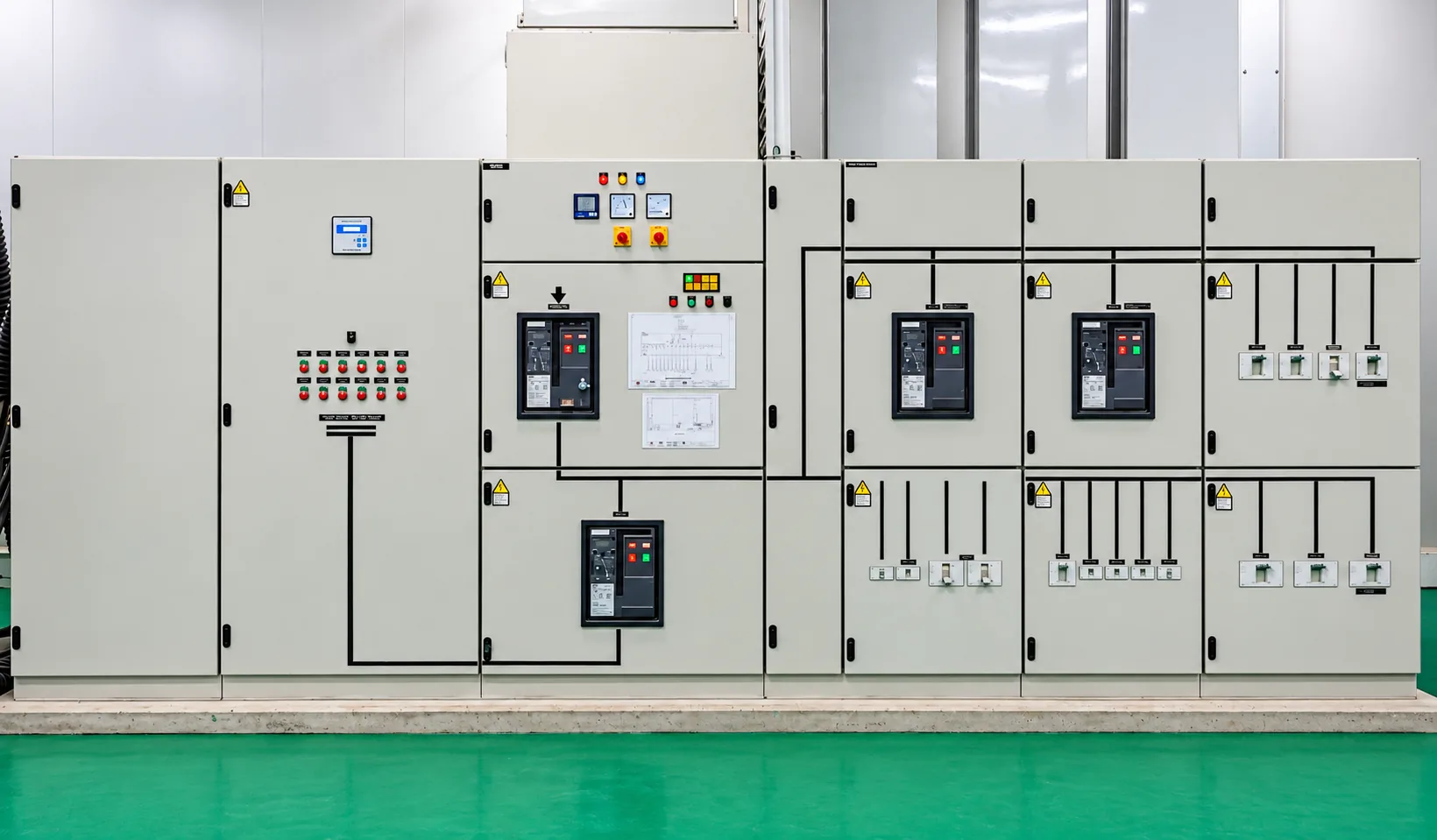
Custom-built LV distribution and control assemblies, configured around project requirements and preferred major-component manufacturers, sourced and coordinated through AdepaTrade.
From main switchboards to transfer, compensation and motor control panels, each assembly is built by a qualified panel-building partner using the component brands approved for your project. Our LV sourcing range extends to assemblies rated up to 6,300 A.
EQUIPMENT SCOPE
LV assemblies we source
Six assembly types, each configured to the project’s single-line diagram, load schedule and approved components.
MAIN DISTRIBUTION
01
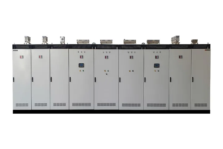
Main Distribution Boards (MDB)
The main LV switchboard after the transformer. It receives the incoming supply and distributes it through the main busbars to the outgoing feeders.
SUB-DISTRIBUTION
02
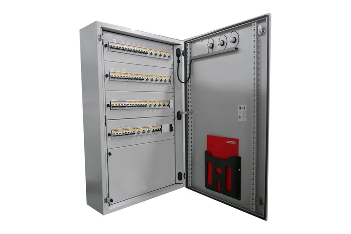
Sub-Distribution Boards (SMDB / PDB)
Boards fed from the main switchboard that distribute power to floors, areas, process lines and final circuits.
TRANSFER
03
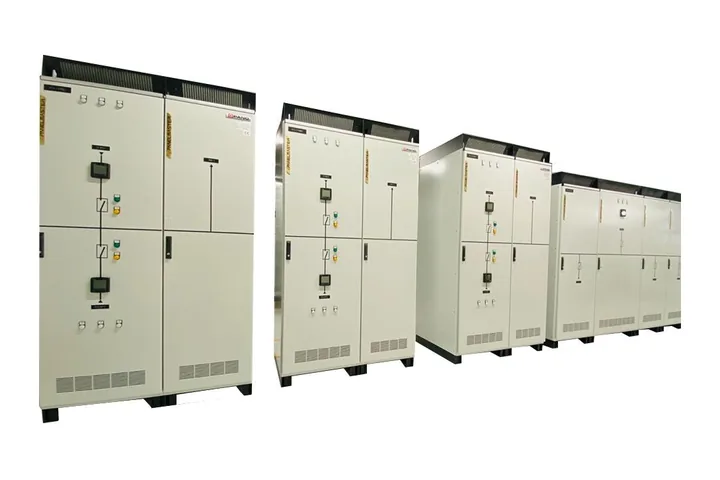
ATS Panels
Automatic transfer switch panels that move the load to a standby source, such as a generator, when the normal supply fails, and back when it returns.
COMPENSATION
04
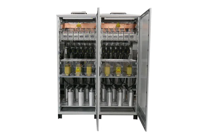
PFC / APFC Panels
Power factor correction panels that switch capacitor steps automatically to hold the target power factor as the load changes.
MOTOR CONTROL
05
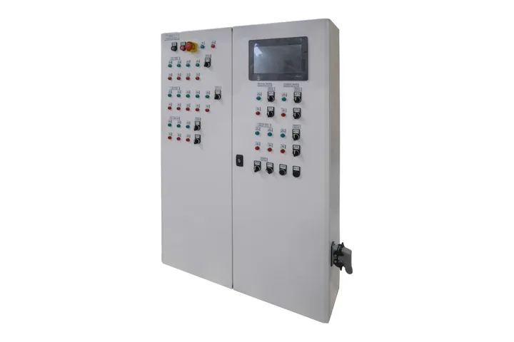
Motor Control Panels
Panels that start, protect and control motors and process equipment, from direct-on-line starters to soft starters and variable speed drives.
PROJECT-SPECIFIC
06
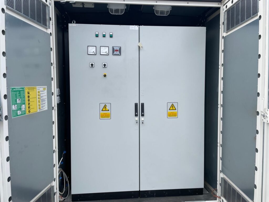
Project-Specific LV Assemblies
LV assemblies built for a particular application or integrated into a wider supply, such as the LV section of a compact / package substation.
APPLICATIONS
Where these assemblies are applied
General applications; each assembly is configured to its project.
Commercial and public buildings
Main and sub-distribution for offices, hospitals, hotels, retail and residential developments.
Industrial facilities
Power distribution and motor control for plants, process lines and auxiliary systems.
Infrastructure and utilities
Supplies for data centres, transport, water and utility sites, often with transfer and backup arrangements.
Energy and generation sites
LV distribution, auxiliary supplies and compensation at generation, renewable and substation sites.
SPECIFICATION
Information that shapes an LV assembly quotation
Each assembly combines the values its project needs; not every option or rating applies to every board. The more of the following a requirement states, the more precisely options can be compared.
Parameter
What it means
Typical specification range
Rated current and voltage
Operational voltage and frequency, and the rated currents of incomers, main busbars and outgoing circuits.
Typically 400/230 V, 50 or 60 Hz. Assemblies up to 6,300 A, subject to assembly design and component capabilities.
Short-circuit withstand and breaking capacity
The assembly’s short-time and peak withstand, and the breaking capacity of its devices, against the prospective fault current.
Confirmed against the transformer rating and network fault level for each assembly.
Fixed or withdrawable
Whether circuit breakers and functional units are fixed, plug-in or withdrawable.
Fixed for most distribution; plug-in or withdrawable where continuity of service and maintenance access require it.
Form of separation
How busbars, functional units and terminals are separated inside the assembly.
Where specified, Form 1 to Form 4b (IEC 61439-2).
Degree of protection
Protection against contact and the ingress of dust and water.
To the installation location, for example IP31 indoors or IP54 in harsher areas (IEC 60529).
Busbars
Material, rating and arrangement of the main and distribution busbars, neutral and earth.
Copper or aluminium as specified, sized for rated current, temperature rise and short-circuit withstand.
Incoming and outgoing feeders
The number, type and rating of incoming supplies, couplers and outgoing circuits.
Single or multiple incomers, bus couplers where specified, and air or moulded-case circuit breaker feeders to the approved schedule.
Metering, protection and control
Measurement, protection, interlocking and signals to building management or SCADA systems.
Energy analysers, protection relays and communication such as Modbus, as required.
IEC 61439 requirements and verification
The standards the assembly is designed and verified to, and the records supplied.
IEC 61439-1 and IEC 61439-2 where specified, with design verification and routine verification records from the panel builder.
Typical ranges are representative, not ratings of any single model, and are confirmed per project.
INTEGRATED PROJECT SUPPLY
Built around your project requirements
The specification decides the assembly.
Single-line diagram, load schedule, fault level and site conditions set what the panel-building partner designs and builds, and which components are sourced for it. When the assembly is sourced together with the transformer and MV equipment, ratings and interfaces stay aligned.
COMPONENT SELECTION
Breakers, protection and control devices from the approved manufacturers, rated to the duty.
ARRANGEMENT AND COMPARTMENTS
Section layout, form of separation and access to suit operation and maintenance.
BUSBARS AND FEEDERS
Busbar ratings and feeder arrangement matched to the incomers and the load schedule.
CONTROL AND PROTECTION
Interlocking, transfer logic, protection and signalling as specified.
MANUFACTURING DOCUMENTATION
Drawings for approval, component schedules and wiring diagrams.
INSPECTION AND TESTING
Routine verification of each assembly, and witnessed factory tests where the project requires them.
IEC 61439 separates two steps: design verification proves the assembly design, by testing, comparison with a verified reference design or assessment; routine verification checks each assembly as built. Both are the responsibility of the assembly manufacturer (here, the panel-building partner) and are confirmed per project.
AdepaTrade sources and coordinates the supply. Component manufacturers supply the devices. The panel-building partner builds and verifies the assembly.
Installation, cable connection and site commissioning are carried out by the project’s appointed contractors and engineers; on request, AdepaTrade can arrange on-site engineering supervision and commissioning support under a separate scope.
We coordinate sourcing across these interfaces.
SUPPLY NETWORK
Major components from established manufacturers
Components are selected from the manufacturers approved for your project. A panel built with a manufacturer’s components is not an assembly manufactured by that manufacturer.


PROCUREMENT PROCESS
From enquiry to coordinated supply
01
Technical enquiry
You share single-line diagrams, load lists, specifications, approved component lists and delivery requirements.
02
Documentation review
We review ratings, fault levels, forms of separation and component schedules against your specification.
03
Partner and component sourcing
We select a suitable panel-building partner and source the major components from the approved manufacturers.
04
Technical-commercial clarification
We coordinate scope, drawings for approval, pricing, test requirements and commercial terms, and clarify deviations before order.
05
Coordinated supply
Manufacturing follow-up, verification records and agreed documentation, then shipment coordination and delivery.
Our documentation review checks the offer against your specification; design approval and engineering responsibility remain with your project engineer.
PROJECT REQUIREMENT
Tell us what your project requires.
We source the solution.
Send the LV data you already have. Customers typically submit:
Single-line diagrams · Panel schedules or load lists · Technical specifications · Approved component lists · Bills of quantities (BOQs) · Project location and delivery requirements
Or email adepa@adepatrade.com